Using a multimeter on a flat-panel TV: the safe basic measurements
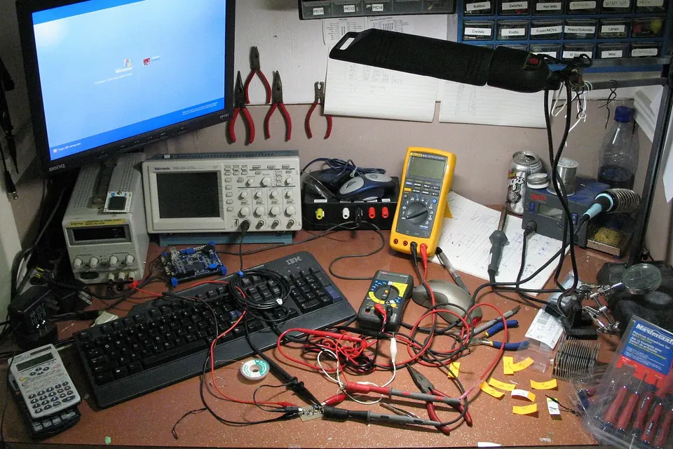
A basic digital multimeter answers most of the questions that matter early in a TV diagnosis: is the main capacitor discharged, is the fuse intact, is the standby supply there, do the main rails come up when the set is switched on? It will not find every fault, but used carefully it stops you buying the wrong board.
Choosing a meter and probes
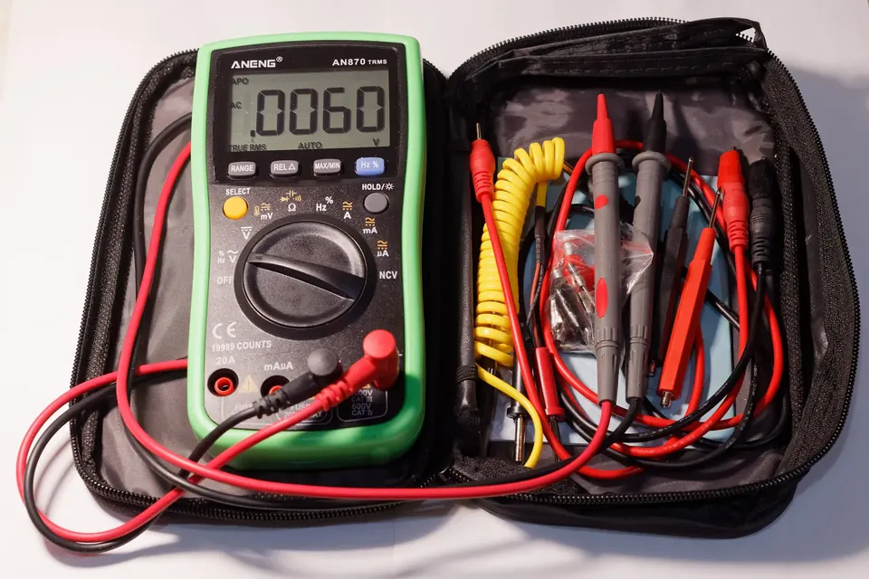
An inexpensive meter is enough for this work if it is properly built. What to look for:
- Measurement category and voltage rating. Meters for mains-powered equipment are rated under the IEC 61010 series of safety standards with a measurement category (CAT II, CAT III, CAT IV) and a voltage, printed next to the input sockets. For work on appliances plugged into a socket, a meter and leads rated at least CAT II for your mains voltage is the minimum; many people buy CAT III for the extra margin. A meter with no category marking is not one to use near mains.
- Fused current inputs. A good meter has fuses on its current ranges, so a mistake does not turn the meter into a short circuit.
- Functions you will use: DC volts, AC volts, resistance, continuity with a beeper, and diode test. Capacitance is a useful extra for components that have been removed from the board.
- Good probes. The UK Health and Safety Executive's guidance note GS38, written for people using test equipment on low-voltage systems, recommends probes with finger guards and only a short length of exposed metal at the tip, and leads that are insulated, flexible and in good condition. Shrouded connectors at the meter end, and clip-on hooks so you do not have to hold probes on a live board, are worth having.
Before you measure: three habits
- Select the function before connecting. Measuring voltage with the meter left on a current or resistance range is the classic way to blow the meter's fuse, or worse.
- Black probe to ground first. On the secondary (low-voltage) side, ground is the metal chassis or a ground pin on the board's connectors. Clip it there and leave it.
- Know which side you are on. Most power boards mark the boundary between the hot primary side and the isolated secondary side with a printed line or hatched area. Unplugged checks can be made anywhere; live checks stay on the secondary side.
Unplugged measurements
Is the main capacitor discharged?
Set the meter to DC volts, on a range above the expected rectified mains voltage, and measure across the terminals of the large filter capacitor on the power board. Only when it reads close to zero should you handle the board. If it does not, discharge it through a suitable resistor as described in the safety guide, then measure again.
Fuses
With the set unplugged and the capacitor discharged, a mains fuse can be checked for continuity. A good fuse beeps or reads close to zero ohms; an open one reads as an open circuit. A fuse that has blown violently, with a blackened or silvered glass, usually means a short somewhere after it, often in the rectifier, the switching transistor or the power factor correction stage. Never replace it with a higher rating or a wire link; see the power supply board for what to check next.
Diodes and transistors, with limits
The diode test function sends a small current through a component and shows the forward voltage. A healthy silicon diode shows a reading in one direction and none in the other; a shorted one reads close to zero both ways. In-circuit readings are often misleading because other components are connected in parallel, so a suspicious reading is a reason to lift one leg or remove the part, not proof of failure.
Resistance and capacitance
Resistance can confirm an open fusible resistor or a cracked track. Capacitance readings are only meaningful on capacitors removed from the board; a bulging or leaking capacitor needs no meter to condemn it.
Live measurements on the low-voltage side
These answer the most useful question in TV diagnosis: is the power supply doing its job? Make every connection with the set unplugged, then power it, read, and unplug again before moving a probe.
Standby voltage
With the TV plugged in but off, a standby supply keeps the main board's microcontroller alive so it can respond to the remote. The standby rail is usually a low voltage, often marked on the board's silkscreen next to the connector that feeds the main board. If it is missing, the fault is on the power board. If it is present and stable, the power board's standby side is working and attention moves to the power-on signal and the main board.
Main rails after power-on
When you switch the TV on, the main board sends a power-on signal and the supply should bring up its main rails, which feed the main board, the audio amplifier and, on many sets, the LED driver. The connector labels usually show which pin carries which voltage. A rail that comes up and then collapses, or never appears, narrows the search: see symptoms and the likely board for how each pattern maps to a board.
What a multimeter cannot tell you
- Signals: the picture data between the main board, the T-con and the panel are fast differential signals. A meter cannot show whether they are correct; an oscilloscope can show activity, but even then diagnosis is mostly by substitution.
- Intermittent faults: a rail that dips for a fraction of a second, or ripple from a tired capacitor, may not show on a meter's display.
- Software: a main board with corrupted firmware has perfect voltages.
Recording what you find
Write down each reading with where you took it: "standby pin 3, set off: present and stable"; "main rail after power-on: comes up then drops". These notes are exactly what a repairer, a forum or a parts supplier will ask for, and they keep you from measuring the same thing twice.
Sources
- UK Health and Safety Executive, GS38: Electrical test equipment for use on low voltage electrical systems, 4th edition, 2015.
- International Electrotechnical Commission, IEC 61010-1, Safety requirements for electrical equipment for measurement, control and laboratory use, and IEC 61010-2-030 (measurement categories); IEC 61010-031 (hand-held probe assemblies).
 Diagnosis
Safety and ESD
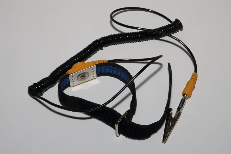
Stored charge, live tests, glass panels and static: how to work inside a TV without hurting yourself or the boards.
 Board by board
The power supply board
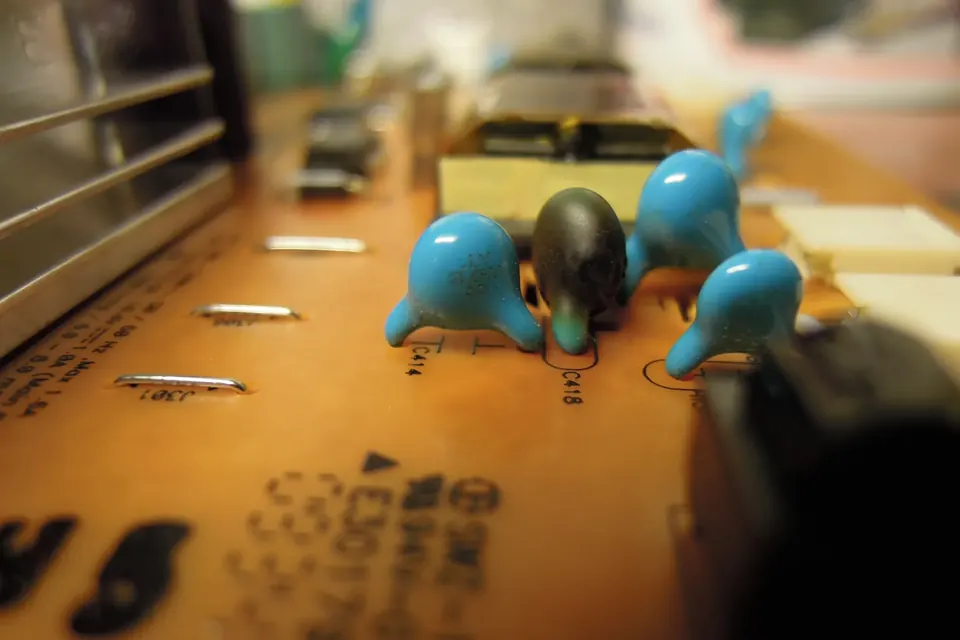
Standby, PFC, main rails and LED driver: the symptoms of a failing supply and the checks you can do safely.
 Diagnosis
Symptoms and the likely board
Dead set, clicking, blinking standby light, lines, no HDMI: which board each symptom usually points to.